Circuit description
A data sheet is the document created by the manufacturer of an integrated
circuit in order to describe the IC to an engineer.
It is intended to let you understand the part well enough to design a circuit
using that part.
Since the manufacturer wants you to buy their parts (particularly if you are
going to manufacture high-volume products that will use lots of their
parts), the manufacturer attempts to make the data sheets both thorough and
accurate.
But the data sheet generally starts out with two things: a fairly simple
overview of the circuit's function, and the part's pin-out.
In the sample data sheet, the circuit description includes a two-sentence
explanation of the part, near the bottom of the first page, as well as a truth
table ("function table") and a logic diagram toward the bottom of
the second page.
The text description describes the NAND function, first as
Y = NOT(A AND B)
(the dot represents the AND function, while the overbar above the "A AND
B" expression negates it), and then as
Y = NOT(A) OR NOT(B)
(the plus sign represents the OR function; note that this is not the
same as binary addition).
Pin-out
The data sheet for an integrated circuit usually contains the part pin-out
fairly early in the document.
As I described in the previous section, this is a diagram of the part's pins,
their numbers and their names.
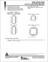
The pin-out for the 7400 appears in the upper left corner of the first page.
It differs from the one I presented in two ways: it is rotated so that pin
1 is in the upper left corner, and the logic symbols are not drawn inside the
box.
Neither layout is more "right" than the other; in fact, my pin-out
drawing pretty closely matches the one in the Digital Logic Pocket Data
Book, also from Texas Instruments!
That one was a quick reference to the pins and their function; in a data sheet
that goes into more detail, omitting the logic diagrams and orienting the
part with pin 1 to the top are common conventions.
But looking at the data sheet, you quickly observe that there are in fact
four different pin-outs shown, and they do not agree!
The upper left one matches the part we used in the last section, but what
tells us that it is the "correct" one, and why are there others?
The answer lies within an important fact: manufacturers often use a single
data sheet to describe multiple similar components.
This one data sheet actually describes a total of twenty components you
could order from Texas Instruments.
(The complete list is on the second page.)
The four different pinouts describe differences in packages.
We are working with the 7400 in a plastic DIP package; the first paragraph of
the data sheet lists the package options and identifies our package as type
"N."
(Note that the "N" designation is specific to Texas Instruments;
different vendors use different notations for package types.)
Each pin-out diagram has a description above it of which parts and packages
match the diagram; the upper left one lists the "N" package type for
the "SN7400."
Part families
The upper right corner of the data sheet claims that this data sheet applies
to six different parts: SN5400, SN54LS00, SN54S00, SN7400, SN74LS00, and
SN74S00.
What is all that about?
These different parts are each members of different families.
They are all two-input NAND gates with enough similarities to fit in a single
data sheet, but actually these six parts are different at the semiconductor
level.
The part we've been talking about is the SN7400; "SN" is a part
number prefix used by Texas Instruments.
(Other vendors may make equivalent parts, and their part number prefix may not
be the same.
For example, ON Semiconductor also uses "SN" as a prefix for the 7400
families, while Fairchild uses "DM" and IDT uses no prefix, as some
examples.
The 7400 logic families are available from a number of different
manufacturers, which is one of the nice things about these parts.)
The SN7400 belongs to the original 7400 family of TTL logic.
The 74S00 family and 74LS00 family each offer some improvements over the
original 7400 parts, with different electrical characteristics.
Texas Instruments also offers these part families in rugged,
extended-temperature versions.
They gave these variants a "54" family designation instead of
"74," and these are again available in all three sets of electrical
characteristics.
Just like the different package options required different pin-out drawings,
there are separate specs in the data sheets for the six different family
versions.
The specs for the 7400 (and 5400) start on page four, the specs for the 74LS00
(and 54LS00) are on page five, and the specs for the 74S00 (and 54S00) are on
page six.
For now just note that for simplicity you generally want to build circuits
using all parts from the same family (7400, 74LS00, and so on) but with
careful attention to the data sheets you can mix families.
Absolute maximum ratings
A data sheet usually has a section called "absolute maximum ratings,"
which basically describes limits beyond which you cause damage to the part.
Note that these are not operating conditions.
The distinction is that when you violate operating conditions, the part may
not work the way it is supposed to, but when you violate absolute maximum
ratings, you have potentially damaged or destroyed the part, and it may not
work the way it is supposed to ever again.
In this data sheet we see that supplying the chip with more than seven volts
is deadly, as is connecting greater than 5.5V to any input.
We also see that there are temperatures below and above which the part may be
damaged.
These would seem to be no big deal (do you expect to work in a room that
violates these conditions?) except that a soldering iron could heat the chip
hotter than that.
The acceptable thermal characteristics for soldering a component are themselves
a complex topic, and manufacturers often offer separate documents describing
the sorts of thermal stresses the part can accept in soldering.
I only mention this to point out that taking a great deal of time soldering
directly to a component, should you try this, is another way to ruin a part.
Recommended operating conditions
The recommended operating conditions describe the environment for which the
part was designed to work: that is, the ground rules for using the part and
expecting the right results.
These tables use a number of conventions for naming their specifications, and
many data sheets expect that you understand what these conventions mean.
This data sheet lists the operating specification for VCC.
There are three columns for the specs, marked "min" (minimum),
"nom" (nominal or ideal), and "max" (maximum).
Not every item uses all three columns, but the VCC spec does: it
shows us that the minimum voltage is 4.75V, the nominal voltage is 5V and the
maximum voltage is 5.25V.
Next we see two specifications for what, as an input, constitutes valid logic
levels.
The VIH spec tells us that a signal must be at least 2V for us to
recognize a logic "1," while the VIL spec tells us that
a signal must be no higher than 0.8V for us to recognize a logic "0."
These tell us that the 7400 accepts a fairly wide range of logic "1"
input voltages, but also tells us that between 0.8V and 2V there is a
"gray area" where we don't know which logic level will be seen.
(Ordinarily this only applies to the time it takes an input to change voltage
levels.)
The next pair of specifications describe the ability of the output of the
7400 to pass electrical current through the output transistors.
IOH tells us that a logic "1" output will allow up to
0.4mA of current to flow to the voltage supply, and IOL tells us
that a logic "0" output will allow up to 16mA of current to flow
to ground.
We also say that the output "sources" 0.4mA and "sinks"
16mA of current.
An application that tried to pass larger amounts of current could cause the
chip to not function properly; a 7400 cannot drive an electric motor, for
example, which might draw hundreds of milliamps.
The last spec in this section, TA, tells us that the part is only
expected to operate between zero and seventy degrees Celcius.
This means that this part is no good for an outdoor application; you would
need an extended-temperature part (like the 5400; look at the temperature
specs for that component).
Electrical characteristics
The recommended operating conditions are what conditions youare
supposed to provide to the chip.
The electrical characteristics are the other side of the contract: if the
part is being treated properly, this is how it will behave.
This table includes specs for VOH and VOL, which are
the voltage levels for logic "1" and logic "0,"
respectively.
The middle column for these specs is marked "typ" (typical);
we expect a logic "1" to be around 3.4V (no lower than 2.4V) and
we expect a logic "0" to be around 0.2V (no higher than 0.4V).
The table also includes specs for IIH and IIL, which
are the amount of current drawn in the detection of logic level "1"
and logic level "0," respectively.
We expect the 7400 to consume a maximum of 0.04mA of current when presented
with a logic "1" input, or consume a maximum of 1.6mA of current
when presented with a logic "0."
(The IIH spec listed µA as the units; one µA is 1,000
mA.)
Data sheets typically offer an ICC spec, which is the amount of
power the part consumes from the power supply.
The 7400's power consumption is quite dependent upon its inputs, so the
data sheet breaks out an ICCH spec for when the inputs are all
"0" and an ICCL spec for when the inputs are all
"1."
The maximum current consumed by the 7400 is the greater of the two specs,
or 22mA.
I skipped two of the specs on the 7400 data sheet, and different data sheets
can include plenty of other specs beyond what we discussed.
However, for the purposes of our discussion the ones I've covered are the
essentials.
Switching characteristics
The last set of specs for the 7400 (top of page five) is the switching
characteristics.
This quantifies the response time of the part.
The 7400 is a simple part, so the only timing specifications are for
propogation delays: when an input changes, how long does the output take
to also change?
The tPLH spec says that when the input conditions change such that
the output must switch from "0" to "1," there is a delay
of around 11ns (22ns maximum) for the change to occur from the time when the
inputs stabilized.
(1ns is one billionth of a second.)
The tPHL spec says that when the input conditions change such that
the output must switch from "1" to "0," the delay is
around 7ns (15ns maximum).
More complex parts can have more complex switching characteristics, but we
will wait until the section on "timing diagrams" before getting
into that topic any further.
Matching up the specs
Probably by now your eyes are glazing at all this generally unexciting
information.
My point here is not to equip you for a semiconductor trivia contest, but
rather to enable you to match up data sheets and see if parts can work
together.
If you connect the output of a 7400 to the input of another 7400 (or the same
one, for that matter), you are comparing the requirements and behaviors of the
two ends of that wire.
If the output is a logic "1," the 7400 is providing a voltage no less
than 2.4V and somewhere less than 5V (we don't know the maximum, except that it
can't possibly exceed the power supply voltage because where would the voltage
come from?).
The connected input needs to see a voltage above 2V and which must not exceed
5.5V... so this is a good fit.
That is, the allowed range is greater than the possible range.
If the output is a logic "0," the 7400 is providing a voltage no
greater than 0.4V. The connected input needs to see a voltage below 0.8V, so
again the fit is good.
When the output is "1," the output will source as much as 0.4mA,
while the connected input only wants a maximum of 0.04mA.
When the output is "0," the output will sink as much as 16mA, while
the connected input only wants a maximum of 1.6mA.
These comparisons are the basis for the claim that a TTL output can feed ten
"TTL loads;" there is enough current at both states to meet the
requirements of ten inputs from the same family.
Now, mixing TTL parts together, you would expect that the inputs and outputs
were designed to be compatible, and the ten TTL load rule gives you an easy
rule of thumb, so you don't need to match up the specs.
However, what if you need to mix parts from different families?
Suppose, for example, that you needed to connect the output from a 74LS00 to
the input of a 7400.
Is that going to work?
Now you need to match up VOH and VOL on the 74LS00 with
VIH and VIL on the 7400.
(Doing this you find that the specs are a little different, but still within
range.)
And you need to match up IOH and IOL on the 74LS00 with
IIH and IIL on the 7400.
(You find that it will work... but the ratio of IOH to
IIL is only 5:1, meaning that you can only drive a maximum of five
7400 inputs, not ten.
This sort of matchup is what I meant earlier when I said that you can mix part
families if you pay attention to the data sheets to see what will (and won't)
work.
Other information
A data sheet can have other sorts of information as well.
Before leaving this section I'll touch on a few other things you might
encounter.
Ordering information tells you how to find the correct part number
for the component you want.
In the 7400 data sheet, we know that we want the 7400, and we want the DIP
package.
The ordering information table on page two tells us the correct Texas
Instruments part number is SN7400N, and that the parts are shipped in
quantity in a plastic tube.
(In case you were wondering, only large volume purchases would go straight
to Texas Instruments.
If you want to buy a single SN7400N, go to a parts distributor like
Digi-Key and look up that specific
number.
Or, if you wanted just a 7400 in DIP form and don't care what manufacturer
made it, go to a electronics hobbyist supplier like
Jameco and just order a 7400.)
A schematic sometimes appears in a data sheet, to describe the workings
of the part to an electrical engineer.
The 7400 data sheet shows the schematic for the TTL, LS and S versions on
page three.
For our purposes this is not important, but if you know enough electronics
to make sense of them you may find them interesting.
Test conditions are often detailed, to qualify the methodology used
in testing the specs in the data sheet.
The 7400 data sheet devotes page seven to describing how the tests are to
be performed.
Package outlines may appear in a data sheet, to show the physical
dimensions of a component.
The 7400 comes in a variety of packages, so pages eight through fifteen give
the package drawings.
(Many manufacturers do not include this in their data sheets, instead
referring you to separate documents that give these drawings, since a package
like a 14-pin DIP is used on a lot of different parts.)
Programming information appears on data sheets for more complex parts
used in computer systems, where you need to not only know the electrical
interface to the component but also the things the part can be made to do
through the interface.
And lastly, data sheets frequently include timing diagrams, which are
the topic of a later section of this course.
Next: 74LS00 Family
Previous: Logic Chips
Copyright ©2003-2006, Mark Bereit. All rights reserved.
|